Cervical Spine Anatomy
The Atlas
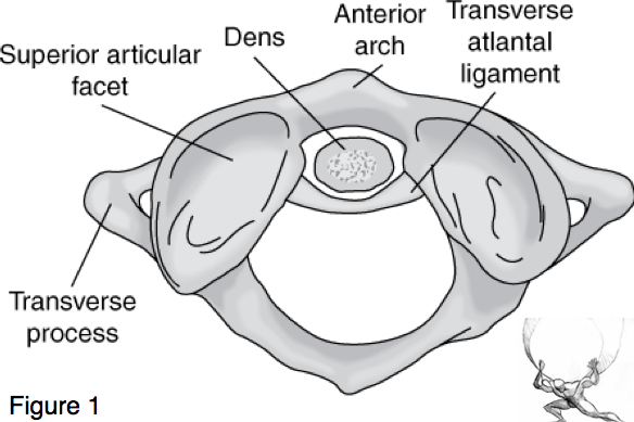
- C1 (Atlas) (Figure 1)- Specialized cervical vertebra devoid of a vertebral body, in its stead is the dens of C2. C1 ring is composed of an anterior arch, lateral masses, and posterior arch. The lateral masses contain the superior and inferior articular facets that articulate with the occipital condyles and C2. The transverse processes project from the lateral masses.The C1 articulation with the occiput allows flexion and extension of the head.
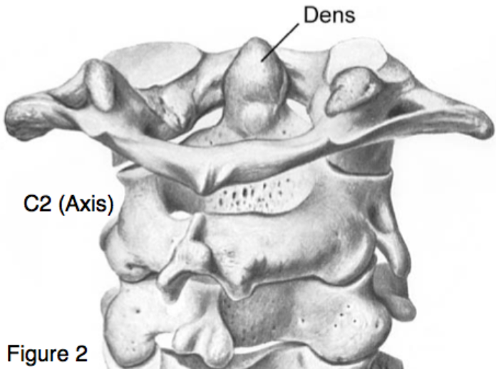
- C2 (Axis) (Figure 2) Specialized cervical vertebrae with projection known as the dens or odontoid process articulates with the anterior
C2 – The Axis
arch of C1. The transverse atlantal ligament (TAL) holds the dens in place against the anterior arch of C1. The C1-C2 articulation allows the head to rotate from side to side.
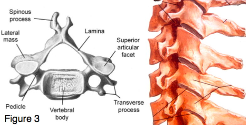
- C3 to C7 (Figure 3) – The vertebral body connects to the lateral masses by the pedicles. The laminae connect the lateral masses to the spinous process. The pedicles, lateral masses and the lamina form the posterior (neural) arch. The superior and inferior articular facets of the lateral masses articulate with the facets of the adjacent vertebrae. The transverse processes project laterally from each pedicle.
C3-C7 Vertebrae
How to Read a C-spine CT: ABCS
Look first at the midsagittal slice, then scroll through the sagittal slices. Next, view the coronal slices from anterior to posterior looking at C1-C2 (cervicocranium) and the lower cervical vertebrae. Finally, review the axial images from the occiput and C1 to C7 and T1.
Cervical Spine Alignment
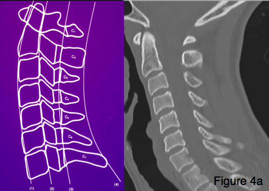
A = Alignment (Figure 4a): 4 smooth curves are formed by the anterior and posterior surfaces of the vertebral bodies, and the bases and tips of the spinous processes. These are best evaluated on the mid-sagittal view.
- Anterior vertebral body line maintained by the anterior longitudinal ligament
- Posterior vertebral body line maintained by the posterior longitudinal ligament
- Spinolaminar line maintained by the ligamentum flavum
- The tips of the spinous processes (less smooth than the other lines)
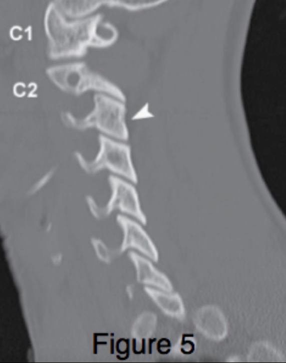
CT C-spine: Parasagittal Slice (Figure 5)
B = Bones: Assess each bone in sagittal, coronal and axial views.
- Mid-sagittal slice
- Anterior and posterior arches of C1
- Dens of C2
- Vertebral bodies of C2 to C7
- Spinous processes of C2 to C7
- Parasagittal slices (Figure 5)
- Lateral masses and articular facets (left and right)
- Coronal slices (Figure 6)
- Dens – fractures and location between C1 lateral masses
- C2 to C7 vertebral bodies
- C2 to C7 lateral masses (posteriorly)
- Axial images (figure 7)
- C1 Ring – anterior and posterior arches, lateral masses, transverse processes and dens
- C2 to C7 vertebral bodies
- C2 to C7 pedicles, lateral masses, transverse processes, lamina and spinous processes
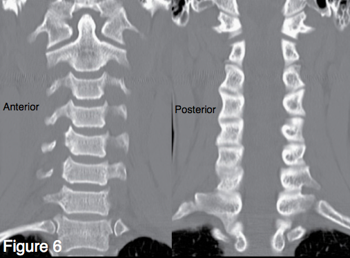
C-Spine CT: Coronal Slices
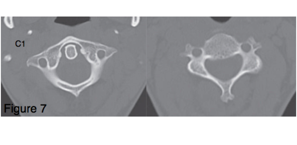
C-Spine CT: Axial Slices
C = Cartilage: Assess the spaces between each vertebra, specifically looking for widening, narrowing or asymmetry.
- Mid-sagittal slice:
- Basion-dental interval (between dens and anterior articular surface of cranium)
- Pre-dental space (between dens and anterior arch of C1) maintained by the transverse atlantal ligament.
- Disc spaces between each vertebral body
- Interspinous process spaces
- Parasagittal slices
C-Spine CT: Axial Images Facet Joints
- Spaces between articular facets
- Coronal slices
- Atlantodental intervals (spaces between lateral masses of C1 and the dens) should be symmetrical
- Disc spaces between each vertebral body
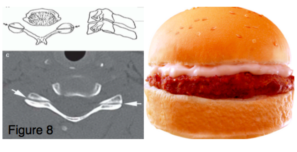
- Axial images (Figure 8)
- Facet joints – “hamburger sign” (Top “bun” is the superior articular surface of the bottom vertebrae, the “patty” is the joint space, the bottom “bun” is the inferior articular surface of the top vertebrae) (Kaji 2013)
C-Spine: Soft Tissue
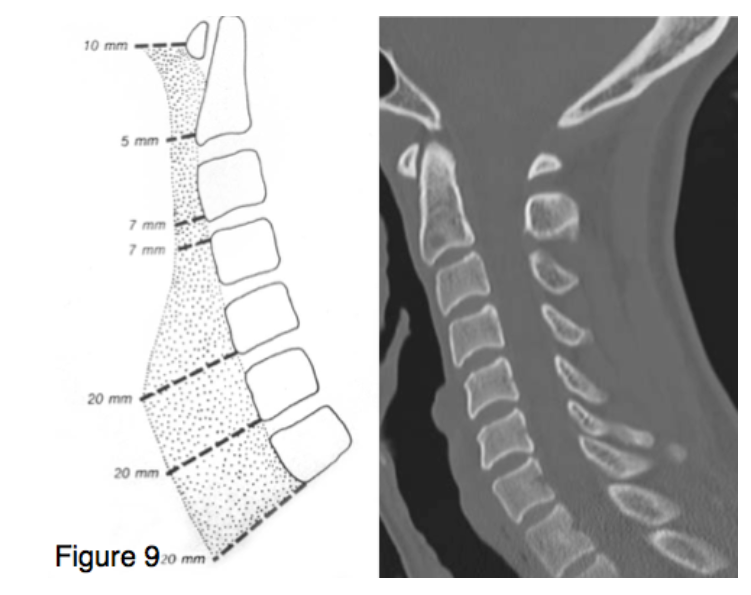
S = Soft tissue (Figure 9)-Examine the pre-vertebral soft tissues in the mid-sagittal slice.
- The soft tissue contour should parallel the vertebral bodies and is narrow from C1 to C4
- The esophagus is interposed within the prevertebral soft tissues starting at C4-C5 so soft tissue thickening is a less reliable sign of injury.
References
Galli RL, Spaite DW, Simon RR: Emergency Orthopedics: The Spine. McGraw-Hill, 1989.
Kaji A, Hockberger RS, Spinal column injuries in adults: definitions, mechanisms and radiographs. In: UpToDate, Moreira ME (ed), UpToDate, Waltham, MA. (Accessed on 12/23/15)
Pope TL Jr, Harris JH. Chapter 5. Cervical Spine Injuries. In: Pope TL. eds. Harris & Harris’ The Radiology of Emergency Medicine. Philadelphia, PA: Lippincott Williams & Wilkins.
Schwartz DT. Section 5. Cervical Spine. In: Schwartz DT: Emergency Radiology: Case Studies. New York, NY: McGraw-Hill, 2008. http://accessemergencymedicine.mhmedical.com/ (via NYU Health Sciences Library)
